Christmas Project: Final Chapter

A little late with the finished product, but I was able to finish my Christmas project before Christmas. I had a custom box built to house all of the components. I was able to mount the relay and the power strips. I used double-sided tape to hold all of the other components down.
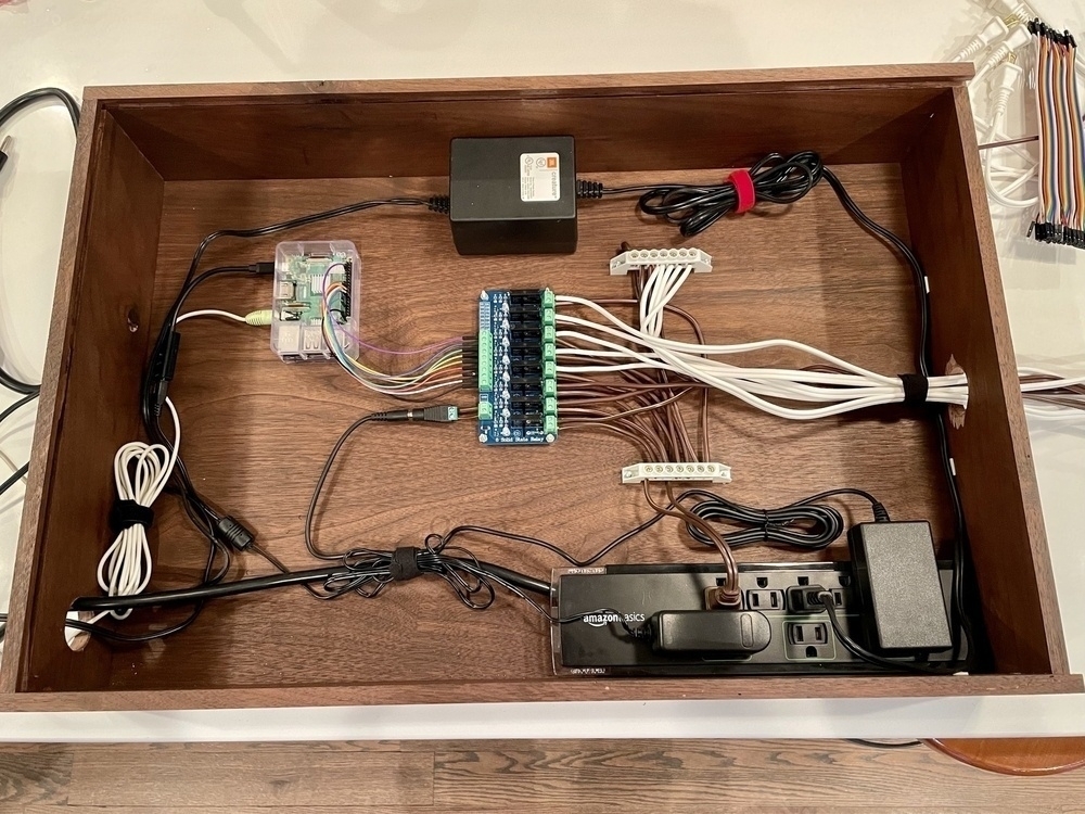
Christmas Project Box

Unfortunately, the relay had a bit of an issue. The first channel would not completely shut off. So the relay would kick that channel on, then the lights would remain lit after kicking it off. I ended up starting a return process with Amazon and they shipped a replacement which made it a few days before Christmas. Unfortunately, the replacement also had an issue: the sixth channel would not work at all (lights would not kick on). I believe I will cancel the return, keep both, and start looking at part replacements. It seems like that component can be replaced with a little solder work and if I can fix these boards, I will have two functioning boards moving forward.

I plan on keeping everything together and adding on in the future. I really need to figure out how I am going to add more sequences in the future. There are websites that sell sequence files, but I would need to update my script to parse those new sequence files. I could also make my own sequences, but that would require me to analyze music file waveforms and come up with patterns myself. This seems to be quite a bit of work, especially for someone like me who is a novice when it comes to working with audio software. Oh well, that is a Christmas 2021 problem.


Christmas Project: Part 3

After finishing the light sequence, I modified the breadboard to wire an LED for each channel. Then I modified the Xmas.py script from the Instructables walkthrough. I then grabbed an mp3 copy of Let it Go from Amazon. Now I am in business.

The next step will be wiring up the relay and stringing up the lights.

Source


Christmas Project: Part 2

The next step for my Christmas project was to setup a breadboard with LEDs and to light those LEDs in a pattern. Once I had one LED working, setting up more was trivial. Now that I have the pattern lit up, I’m ready for the next part.

Source


Christmas Project: Part 1

We have friends who put out a huge Christmas light display every year. The lights are connected to a computer and that computer will drive a light show that is synchronized with music. They also invested in an FM transmitter to broadcast the music to cars who want to stop and watch the show. I have always loved this idea and have often entertained the notion of putting together our own light display. Unfortunately, we live in the rear house of a two house lot, which means we have no street visible area for a light show. We still put out Christmas lights every year, but these lights are mostly for us to enjoy as no one else will see them. I had mostly given up the idea of putting together a large light project. However, this year I stumbled across this: Raspberry Pi Christmas Light Show. After I saw this project, I knew I wanted to try and put one of these together for our house.

I made a hard sell to Max. My idea was to have a project we could work on together. After he agreed, I ordered the parts. The parts arrived the weekend after Thanksgiving and we started to test out a few things. We started by prepping the Pi, which means we had to apply the heat sinks, and install Raspberry Pi OS on an SD card. I had already purchased an Adafruit console cable for when I bought my first Pi to setup our Pi-hole. Connecting the console cable is a cinch:

Black -> GND
White -> TXD
Green -> RXD

If you’re connecting to the Pi through the console cable on a Mac, you’ll need to install drivers. If you’re connecting to the Pi through the console cable on Linux, the drivers should already be installed (or at least were for me on Pop!_OS). You can just use screen to connect:

$ sudo screen /dev/ttyUSB0 115200

The ttyUSB0 might be different on your setup.

After ensuring we could connect to the Pi, it was time for our Hello World equivalent: wire a push button and LED on a breadboard through the GPIO pins and write a simple Python script to run the circuit. When the push button is depressed, the LED should emit light; when the push button is released, the LED should not emit light. After setting up this test, I demonstrated it to Max. He was nonplussed; tough crowd.

Source